INSARAG Marking and Signalling System
INSARAG Marking System
Marking systems are an essential tool used in USAR operations to display and share key information between rescue teams and other field personnel. They should also be a mechanism to strengthen coordination and minimise duplication. To maximise the value of using a marking system in an event it is necessary to identify and universally use a single, common method. For this method to be effective, it must be used by all responders, remain simple to apply, simple to understand, be efficient in the use of resources and time, communicate the information effectively and be consistently applied.
The INSARAG Marking System strives to achieve these things and consists of three principle Marking elements, these being: Triage Marking, Victim Marking and Rapid Clearance Marking (RCM). These components deliver a comprehensive suite of visual displays that capture critical information to both inform situational awareness and support planning and coordination.
The INSARAG Marking System is used by teams as the default marking system in the absence of any national system in countries where operations are occurring. Marking system use will be determined by the LEMA in liaison with the UCC.
Countries are encouraged to use the INSARAG Marking system as their national standard which will assist in times of crisis when international teams are required to be used. The INSARAG Marking System is designed to complement not compete with national systems.
The following is defined:
- General Area Marking (optional)
- Structure Orientation (optional)
- Cordon Markings (optional)
- Worksite Triage Marking (required)
- Victim Marking (required)
- RCM (optional)
General Area Marking
At times some general marking will be required to be applied to assist in navigation and coordination. This should be limited to essential information only and be as concise as possible.
- General area marking can be applied using spray paint, builders’ crayon, stickers, waterproof card etc. as determined by the team. The colour should be highly visible and contrasting to the background
- It may include:
- Address or physical location
- Landmark or code name (e.g. sugar factory building 1)
- Assigned area or worksites are to be identified individually (see Worksite Marking)
- If no maps are available, sketch maps are to be produced and submitted to the UCC/LEMA.
- When producing maps, primary geographical identification should be the existing street name and building number, when possible. If this is not possible, landmarks should be used as reference and should be used universally by all actors
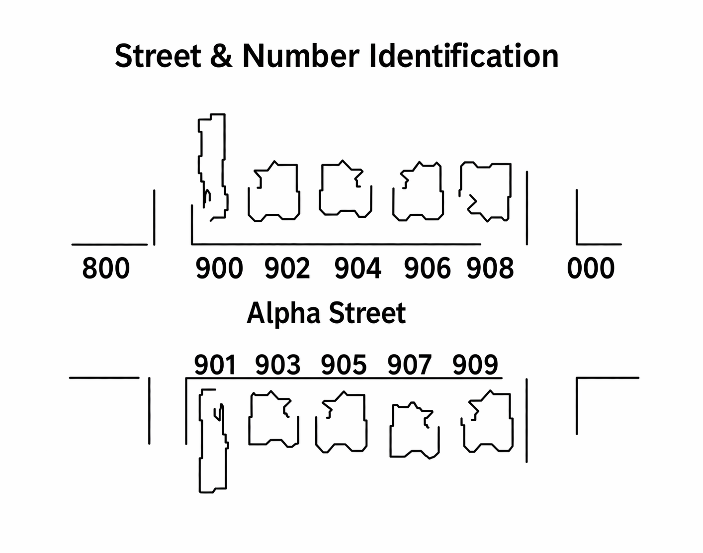
Structure Orientation
Structure orientation is an optional way of marking. It includes both an exterior and interior identification:
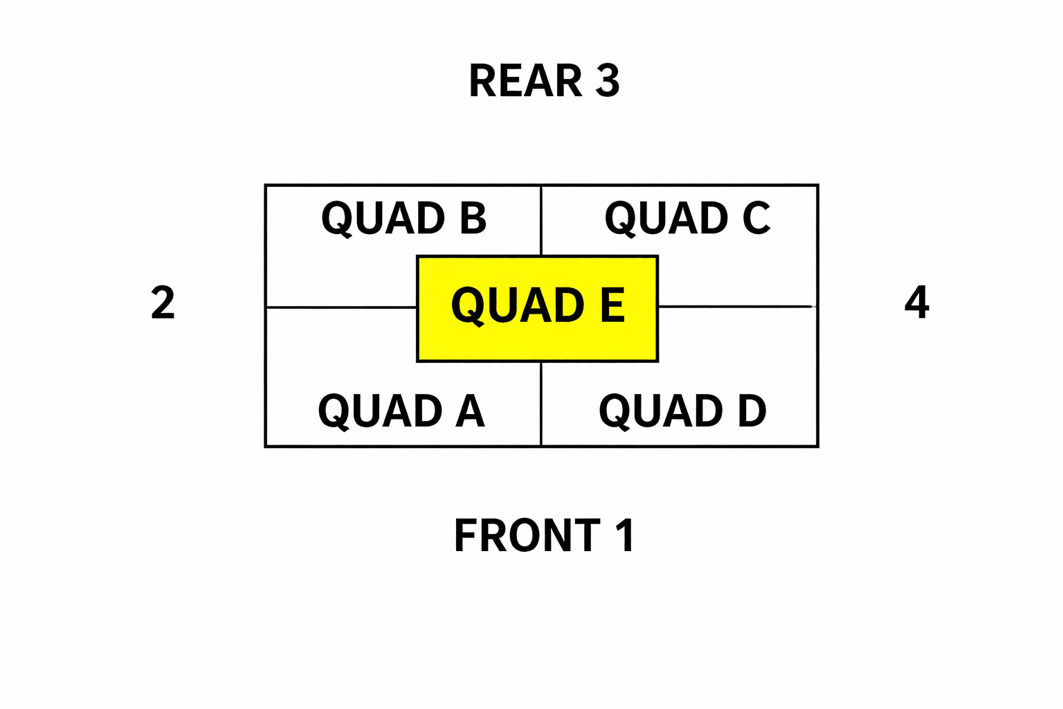
- Exterior Identification: The street address side (front) of the structure shall be defined as “1”. Other sides of the structure shall be assigned numerically in a clockwise manner from “1”.
- Interior Identification: The interior of the structure will be divided into quadrants. The quadrants shall be identified alphabetically in a clockwise manner starting at the corner where Side 1 (front) and 2 meet. Quadrant E (central lobby, elevators, staircases, etc) applies to buildings with multiple storeys.
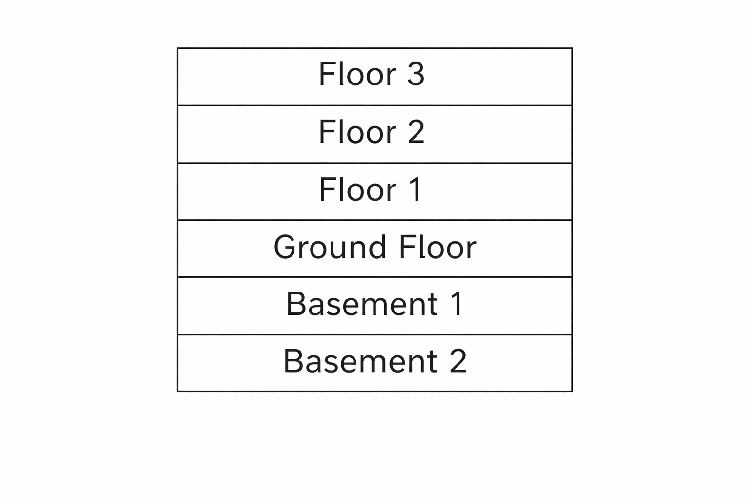
Multi-storey structures must have each floor clearly identified. If not obvious, the floors should be numbered as viewed from the exterior. The ground level floor would be designated the “ground floor” and, moving upward the next floor would be “Floor 1”, etc. Conversely, the first floor below ground level would be “Basement 1”, the second “Basement 2”, and so on.
Cordon Markings
Cordon markings can be used as an option to identify operational work spaces as well as hazardous areas to restrict access and warn of dangers.
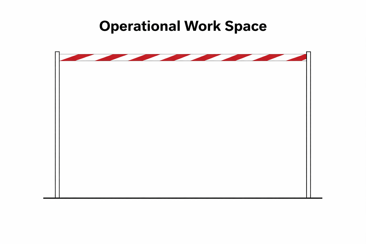
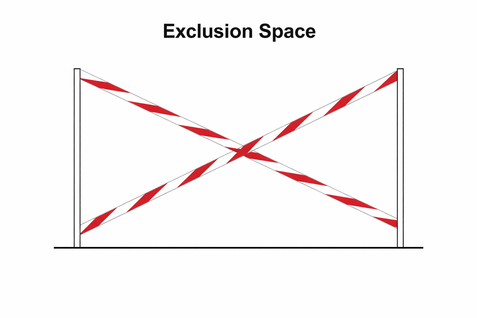
Worksite Triage Marking
Worksite triage marking was originally developed to enable teams to communicate to other teams that they have already worked in a building and thus avoid duplication of effort. The marking system has since developed as a two-step communication. First of all, a communication for triage teams to mark structures that they have identified as viable worksites, and secondly, the original intent of communicating which teams have completed their work in the building.
The much improved ICMS system has reduced the need for a building marking system due to better coordination and communication among teams but is still deemed an essential part of the coordination system as it displays critical information, is simple to understand and apply, and allows Worksites to be easily recognised.
The marking should be placed near the point of entry on the exterior of the collapsed structure that offers the best visibility, in the front, (or as close as possible) or main entry to the worksite. Whilst key information is required, teams can exercise discretion and adapt to environmental impacts within these boundaries whilst still maintaining a common, effective and consistent marking system. The system should complement the LEMA/national systems and can be adapted to work alongside these as required.
Markings can be made in any colour clearly contrasting to the structures surface, making it highly visible at any time.
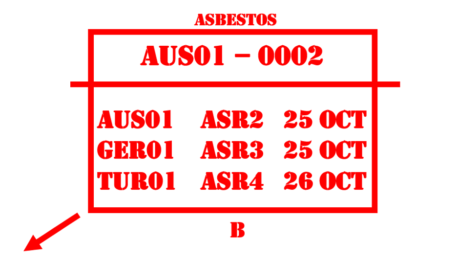
Example of a completed worksite marking system, with all required work completed:
Marking Method
Worksite marking should be applied during initial ASR Level 2 Sector Assessment after a site has
been triaged to be a worksite. The marking should be applied to the front, (or as close as possible)
or main entry to the worksite. See Worksite at Coordination for more information on Worksites and Worksite ID. The following method should be used when applying worksite marking:
- May draw a directional arrow to confirm exact location of worksite/worksite entry
- Inside box – displays:
- Worksite ID (app. 40cm. font)
- Team ID (app. 10 cm. font)
- ASR Level completed (app. 10 cm. font)
- Date
- Outside of box – displays:
- Any hazard requiring identification e.g. Asbestos (top)
- Triage category (bottom)
- Arrow pointed to the exact location of (the entry of) the worksite
- Updated with Team ID, ASR Level completed and date as further levels of work (ASR) are completed
- Material used can be spray paint, builders’ crayon, stickers, waterproof card etc. as determined by the team
- The Worksite ID should be approximately 40cm high
- Draw a box around the painted text (approximately 1.2 to 1.0 metres)
- After all work on the worksite has been completed and it is determined no further work is required a horizontal line is to be drawn through the entire worksite marking, below the worksite ID and above the ASR Levels completed
- If it is absolutely determined a building only holds deceased the marking is with ASR5 and the horizontal line as described above only
If a team considers there is a need to leave critical additional information at the worksite this can be added to the worksite marking using plain language in full view when required. This and all other relevant details should be recorded on the Worksite Triage or Worksite Report forms and submitted through the ICMS.
Progressive Examples
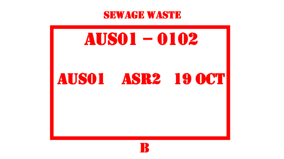
Worksite AUS01-0102, Australia 1 completed ASR 2 Sector Assessment on the 19th of October. Sewage waste was identified as a hazard. Triage categorie determined as "B".
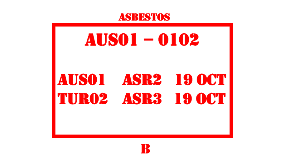
Here the Türkiye 02 team were assigned to ASR3 operations on the AUS01-0102 worksite following the Sector Assessment (ASR2) completed by Australia 01. Türkiye 02 completed ASR3 Rapid SAR operations on the 19th of October.
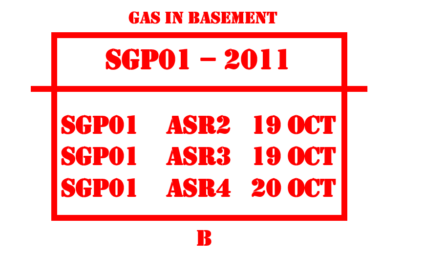
Singapore 01 team has completed work at worksite AUS01-0102 on the 20th of October.
In the figure above, the Singapore 01 team has completed work at the worksite AUS01-0102. A hazard warning about gas leaking into the basement has been added in plain language. Triage category determined as “B”. Operations to ASR2 and ASR3 were completed on the 19th of October. Operations to ASR4 Full SAR were completed on the 20th of October. No further operations are required on this worksite.
Practical examples
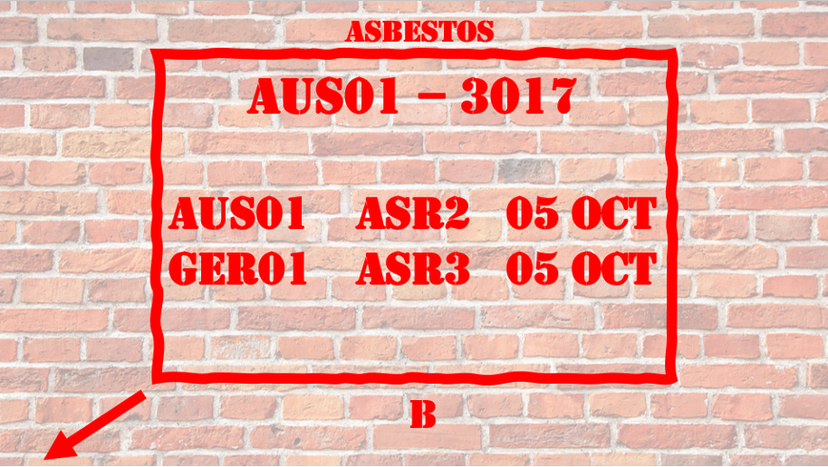
Australia 01 have completed an ASR2 Sector Assessment at the specific Worksite AUS01-3017 on the 5th of October. An arrow has been added to the marking to make it clear that AUS01-3017 is to the left and below the marking. A hazard warning identifying asbestos has been added in plain language. Triage category determined as “B”.
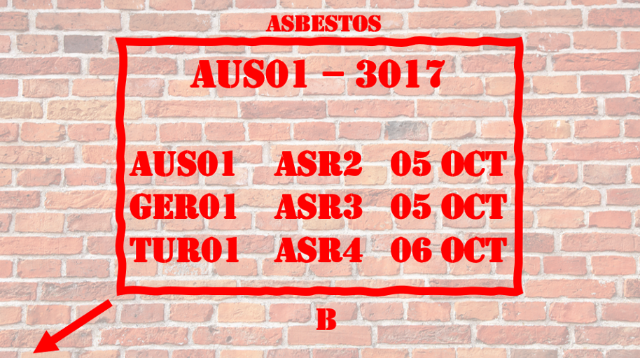
Türkiye 01 were assigned to complete an ASR4 on the AUS01-3017 worksite following the ASR3 Rapid SAR completed by Germany 01. Türkiye 01 completed ASR4 Full SAR operations on the 6th of October.
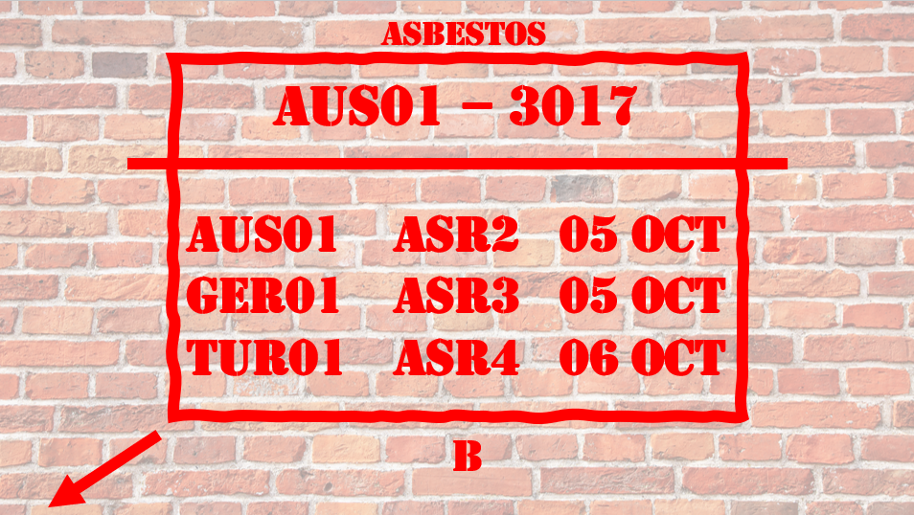
Türkiye 01 having completed ASR 4 Full SAR on the AUS01-3017 worksite, having determined no further work is required on this worksite. Marking has been updated with horizontal line through the centre.
Victim Marking
Victim marking is required to identify potential or known casualty (live or dead) locations that are not obvious to rescuers e.g. below debris/entombed.
Marking Method
The following method should be used when applying victim marking:
- When teams (e.g. Search teams) are not remaining on site to immediately commence operations
- At incidents involving multiple casualties or where any confusion on exact location from search operations is possible
- Markings are done as close as physically possible to the actual surface point identified as the location of the casualty
- Material used can be spray paint, builders’ crayon, stickers, waterproof card etc. as determined by the team
- The size should approximately 50 cm
- The colour should be highly visible and contrasting to the background
- Not intended for use when rescue operations are completed
- Not to be applied to the front of a structure with the Worksite ID unless that is where the casualties are located
Progressive Examples
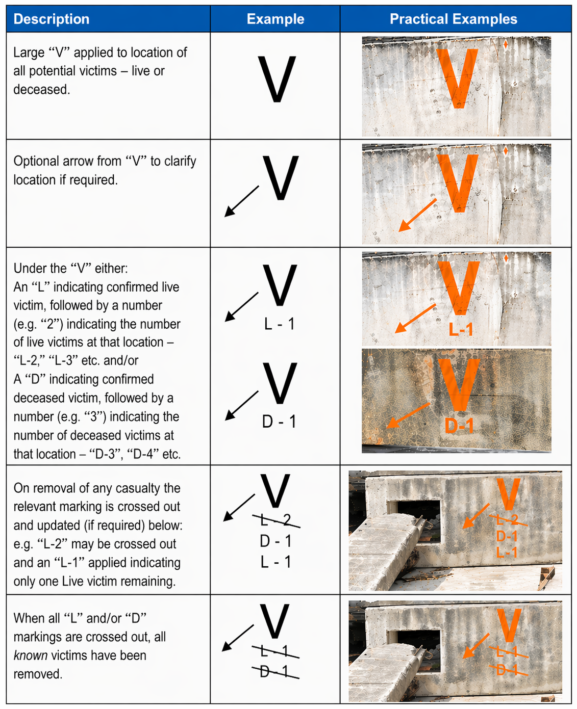
Rapid Clearance Marking System
The triage category and marking system is mainly used for potential live rescue sites but can also include triage category D to allow triage teams to identify buildings that the teams have reason to believe that there are only deceased remaining in the building and no rescues are possible. This applies to ASR2. However, after having completed ASR5 where teams have established there are no live victims or “Deceased Only” it may be beneficial to mark the site accordingly. Leaving a recognised “Clear” marking will prevent duplication and have other advantages.
This type of marking is called Rapid Clearance Marking (RCM).
Marking Method
The process for applying RCM is as follows:
- A decision must be made by the LEMA to implement this level of marking
- RCM can only be used when sites can be fully searched quickly or there is strong evidence confirming no live rescues are possible
- Two RCM marking options are available, they are: “Clear” and “Deceased Only”
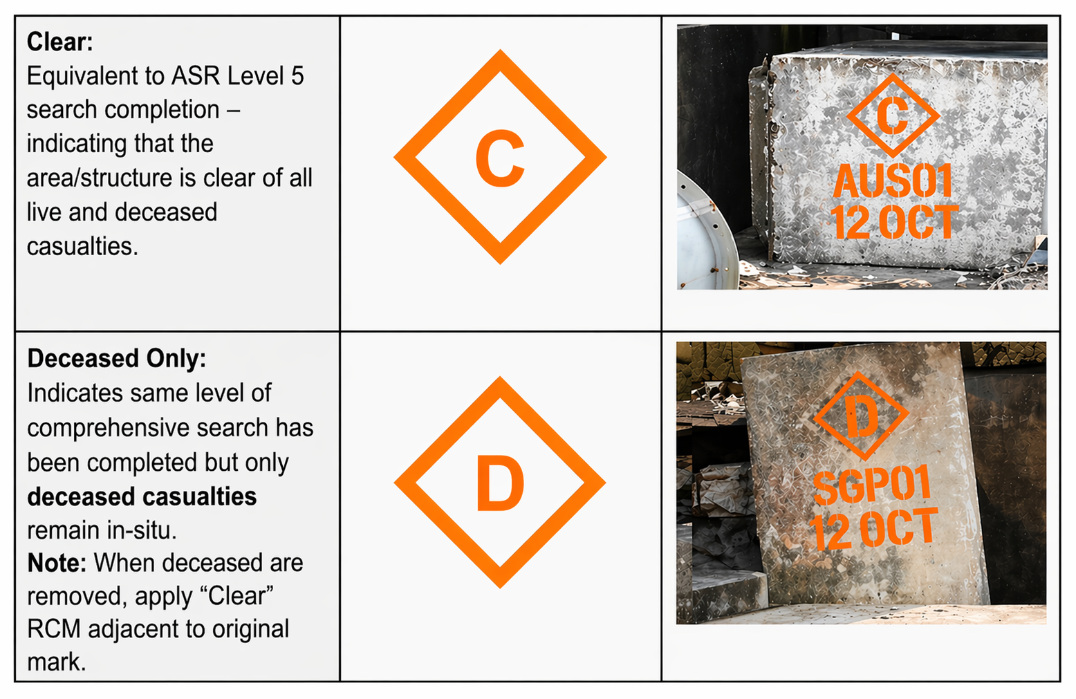
- Can be applied to structures that are able to be searched rapidly or where information confirms there are no live victims or only deceased remain.
- Can be applied to non-structural areas – cars/objects/outbuildings/debris piles etc. – that have been searched to standards indicated above.
- Applied in the most visible/logical position on the object/area to provide the greatest visual impact
- Diamond shape with a large “C” inside for “Clear,” or with a large “D” inside for “Deceased
Only.” Immediately below, the following is applied:
- Team ID: _ _ / _ e.g. AUS01
- Date of Search: _ _/ _ _ _ e.g. 19 Oct
- Material to be used can be spray paint, builders’ crayon, stickers, waterproof card etc. at the discretion of the teams.
- Size: Approximately 20 cm x 20 cm
- Colour: Bright, contrasting colour to background
Progressive Examples
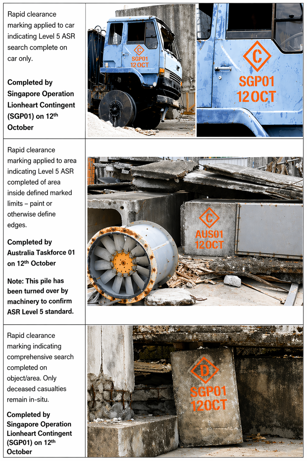
Team Function Identification
- Response team identity (country and team name) by uniform, patch, etc.
- Personnel – the following positions must be colour-coded and labelled in English plain text (vests, arm bands, helmet colour, etc.)
- Management position(s) – white
- Medical position(s) – red cross/crescent
- Safety/security position(s) – orange
- Vehicles must be marked with team name (flag, magnetic sign, etc.)
INSARAG Signalling System
Effective communications underpin safe field operations, particularly in multi-agency environments. This is even more critical in international environments where language and cultural differences also exist. Effective emergency signalling is essential for safe operation at a disaster site. Having a universally understood emergency signalling system ensures that all personnel operating on a worksite know how and when to react to signals on the site to ensure safe and effective operations for rescuers and victims alike. The following steps must be considered:
- All USAR team members should be briefed regarding emergency signals
- Emergency signals should be universal for all USAR teams
- When multiple teams are operating on a single worksite, this common understanding should be reinforced to all personnel involved
- Signals must be clear and concise
- Team members are required to immediately respond to all emergency signals
- Air horns or other appropriate hailing devices should be used to sound the appropriate signals as follows and located to allow immediate use
Evacuate
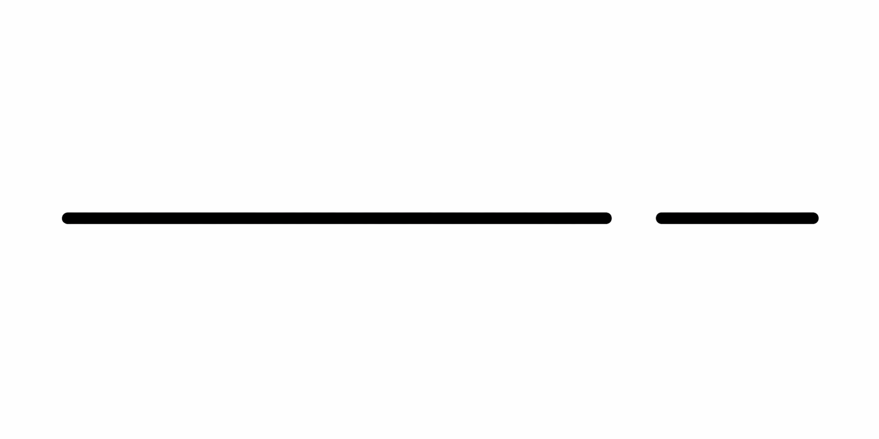
Three short signals, one second each - repeatedly until site is cleared.

Cease Operations - Quiet
One long signal, three seconds long.
Resume Operations
One long signal + one short signal.